12.7 GPU Particle Systems
12.7.1 Introduction
This tutorial will be focused on creating a GPU based particle system using TouchDesigner and GLSL shaders. This has many benefits compared to using the built-in Particle SOP, because all the computations inside of GLSL shader are performed on the GPU. GLSL shaders allow for the creation of particles systems with extremely large particle counts (in the multi-millions and more), with customized behaviour, that still compute quickly.
The process to achieve a particle system in GLSL can be slightly confusing at first, compared to just creating a Particle SOP, but once you understand the basic principles behind the workflow, you will have infinite freedom to experiment.
One concept to understand is that the GLSL material shader we'll be using cannot create new points out of thin air, so you have to feed it a set a starting points that correspond to the maximum number of particles in your system. The amount of points feeding in determine the number of times our material shader will compute and the shader code we write will be applied to every single particle individually.
A second important concept to remember is that similar to any other type of shader, your code has no reference to anything other than the current point it is processing. The shader will not have a reference of the previous or next frame, and wont have any reference to any points that have been computed on that same frame. All the shader code will need to be standalone and any referential data will need to be fed to the shader as either a texture or value uniform. A uniform is a parameter or value that you will pass to your shader code. This is important because the particles in a particle systems need to know their previous position at last compute, so that they can then re-apply their code to compute their new position on the next frame. In other OpenGL applications, you'd create multiple texture buffers that you would ping-pong between reading and writing. In TouchDesigner, this be solved by using a simple feedback loop.
To achieve the goal of creating a fully-functioning GPU particle system, we will break the particle system into a number of incremental projects.
12.7.2 Moving Particles with Textures
Before getting started, this is an outline of the steps to this section:
Create a set of points that will be your initial positions
Add a point index to each point
Use a Noise TOP to create 1000 RGBA channels to use as point positions
Create a GLSL TOP to scale the values of the Noise TOP (will be built upon later after we remove the noise)
Create a basic render setup
Create a GLSL Mat that will hold all of the shader code for the particles
Create a basic pixel shader to shade all pixels white
Create a vertex shader with uniform inputs and correct outputs
Get the pointIndex, point position texture, and then the points per instance
Sample the Noise TOP texture and create UV co-ordinates
Move the incoming points from using all the above steps
The first thing we need to do is create a set of points that will be used by the GLSL MAT as the particles. As mentioned earlier, a GLSL MAT cannot create particles on its own. It is simply a bit of code that gets applied onto every point that is given to it. For the particle system this means that we need a piece of geometry with 1000 points to have a particle system with 1000 points. Similarly if we wanted a particle system with 1,000,000 points, we would need a piece of geometry with 1,000,000 points. To start simply, we're going to generate 1000 points at the origin 0,0,0.
You can follow along with the explanation below by opening example '01_Moving_particles_with_textures.toe'.
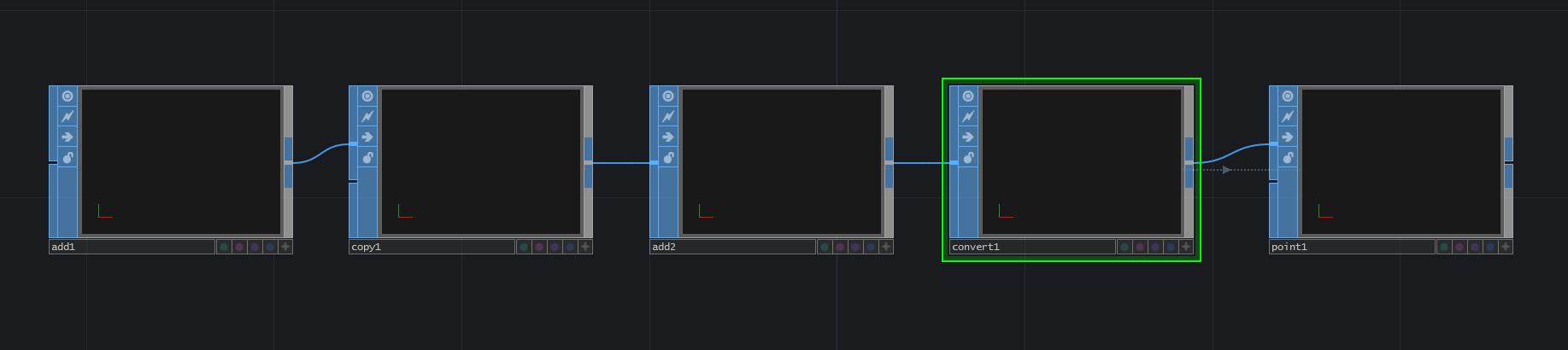
Start by creating an 'Add SOP' and clicking the first checkbox in the parameter window to enable 'Point 0'. The default values of 'Point 0' will work for this example. This creates our first point. Connect the output of the 'Add SOP' to the first input of a 'Copy SOP'. The 'Copy SOP' is used to copy the first point created by the 'Add SOP', giving us more points for our particle system. Do this by changing the 'Number of Copies' parameter of the 'Copy SOP' to 1000. Now we have 1000 points to create a 1000 point particle system.
Connect the ouput of the 'Copy SOP' to the first input of another 'Add SOP'. This 'Add SOP' will be used to close the points and create a polygon. This is to create a polygon from our 1000 points that can be converted into particles before entering the shader. To do this, in the new 'Add SOP' (which should be named 'add2' if you're using the default operator names) go to the 'Polygons' tab in the parameter window, and add an asterix ('*') to the first parameter named 'Polygon'. Now we'll convert this 1000 point poygon into particles. Do this by connecting the output of the second 'Add SOP' ('add2') to a 'Convert SOP'. In the new 'Convert SOP', change the parameter named 'Convert To' to have the value of 'Particles' and change the parameter named 'Particle Type' to 'Render as Point Sprites'. Creating point sprites allows us to use a single line of shader code to increase the particle size later.
The final step before creating out material is to create an additional custom attribute using the point indices. To do this, connect the output of the 'Convert SOP' to a 'Point SOP'. Set the first 'Custom Attrib' name to 'pointIndex'. Select 'float' as the data type from the dropdown to the right of the name field. Expand the 'Value' field, and in the first parameter field named 'custom1val1', enter the Python script:
me.inputPoint.index
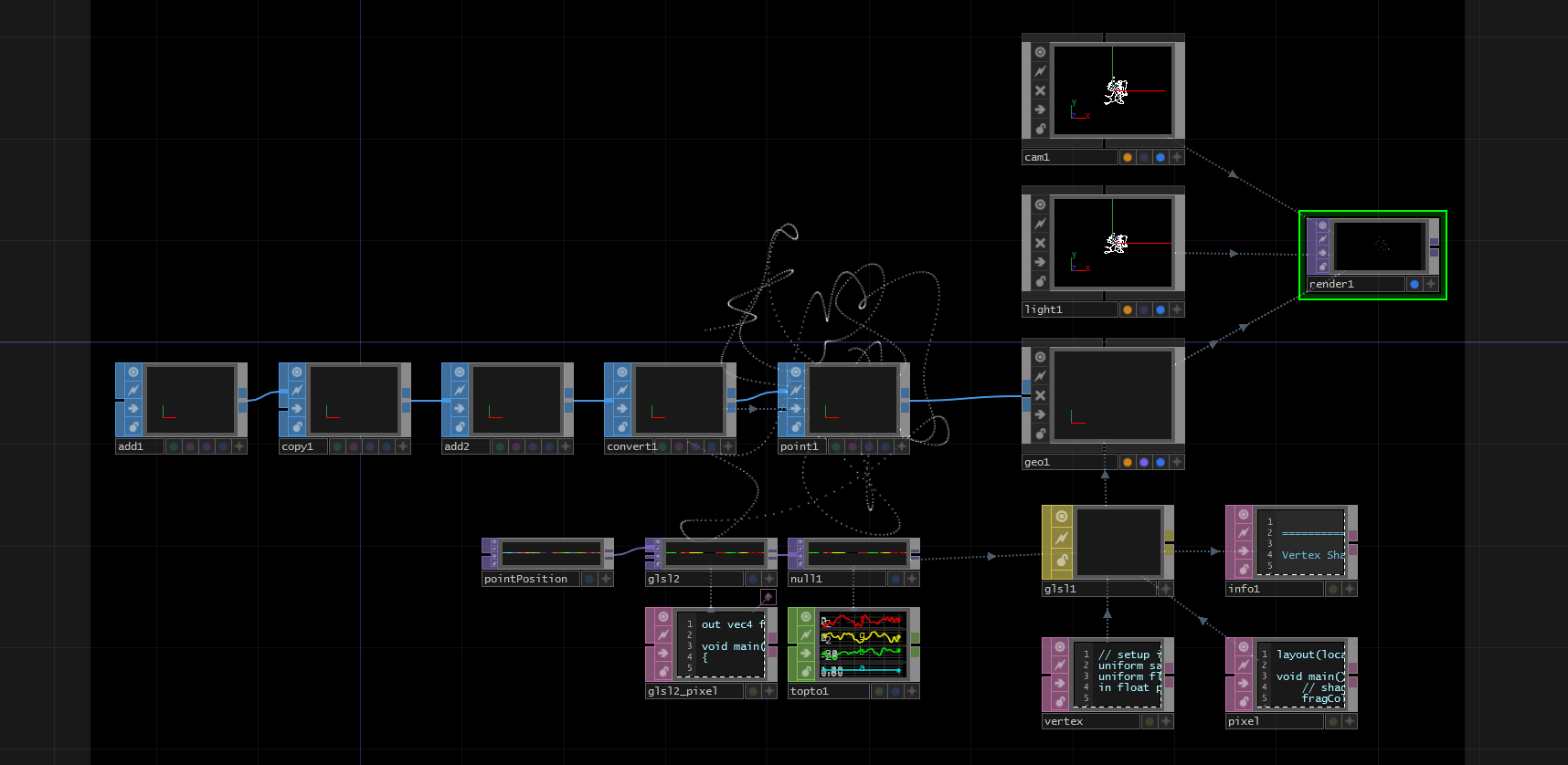
What this does is create a custom attribute on each point that we can use in the GLSL code. In this case, we've taken the point index of each point, and assigned it to a float value named 'pointIndex'. Now we've finished the first two steps, and we have 1000 particles that we will feed into the GLSL MAT. This should look like this (Note: You will not see anything in your SOP viewers at this stage unless you activate different display options to make points visible!):
{width=100%}
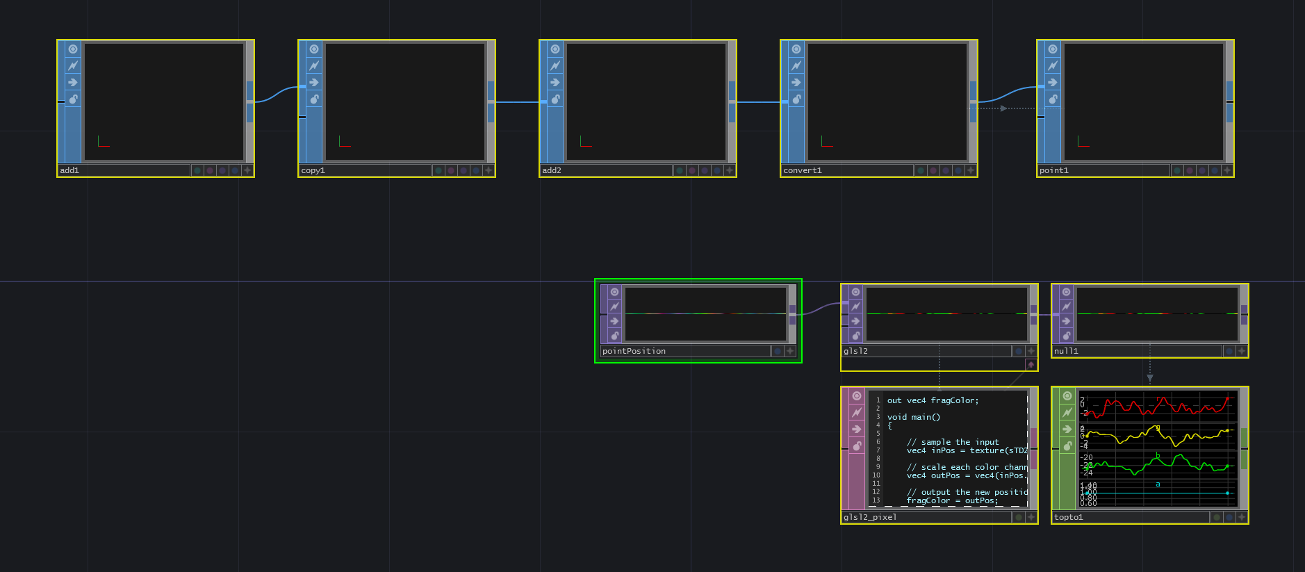
The next thing we're going to do is create some noise that we will use as our point positions. The first thing to do is create a 'Noise TOP'. In the 'Common' parameters, change the resolution to 1000 pixels by 1 pixels and the 'Pixel Format' to '32-bit float (RGBA)'. This gives us one pixel of noise for every particle we have (1000 pixels of noise for 1000 particles). Changing the 'Pixel Format' to '32-bit float (RGBA)' means that every pixel will have 32-bits per color channel, meaning a lot more precise data can be held in each color channel. The next step is to set the 'Monochrome' parameter to 'off'. This returns a different noise value for each of the color channels, which will be translated into different noise values for our X,Y,Z positions of the particles. You can then choose to animate the noise however you like for the example, but the easiest is the add the following code to the 'Translate' parameter's 'tx' value:
absTime.frame/100
This will transform the noise along the X axis, which will create a ribbon-effect on the initial particle system. Next we're going to create a 'GLSL TOP' that will allow us to have more fine tuned control over the current noise values in each color channel. We'll be able to scale those values, and then in further sections, expand on the same shader to add more functionality. Connect the output of the 'Noise TOP' to the first input of a 'GLSL TOP'. The 'GLSL TOP' is created by default with a 'Text DAT' docked to it, with a default shader that outputs the color white. Edit the 'Text DAT', erase the existing code, add the code below, and then save it:
out vec4 fragColor;

void main()
{
// sample the input
vec4 inPosition = texture(sTD2DInputs[0], vUV.st);

// scale each color channel (the XYZ of the vector) separately
vec4 outPosition = vec4(inPosition.x * 5.0 - 2.5, inPosition.y * 5.0 - 2.5, inPosition.z * -5.0 - 20.0, 1.0);

// output the new position
fragColor = outPosition;
}
We'll quickly review the code above, but please refer to previous sections in this chapter. We first setup the main output 'fragColor'. We then sample the texture at the current UV. Because we setup the 'Noise TOP' to have the same number of pixels as there are particles, we can then sample the pixels on a one to one basis for each particle. After we sample the current pixel, we scale the R and G channels (the X and Y of the vec4) by 5.0 and then translate them 2.5 units to the left and down of the camera. We then we scale the B channel (the Z of the vec4) by -5.0, and then translate it 20 units away from the camera to fit the whole particle system in the scene. We can leave the alpha channel at 1.0 as we currently wont be using it.
After the scaling and translating, the 'outPosition' is assigned to the 'fragColor' output. If you'd like to see the positions that the particles will be receiving, you can connect the 'GLSL TOP' to a 'TOP to CHOP' operator and view each color channels values. This finishes step 3 and 4 of the item list.
{width=100%}
Now create a basic render setup by adding a 'Camera COMP', a 'Light COMP', a 'Geometry COMP', and a 'Render TOP'. They can all be set to their default values for this exercise. Make sure to add an 'In SOP' to the 'Geometry COMP' so that you can input your set of points and turn on the render and display flags on the 'In SOP' inside of the 'Geometry COMP'. That will complete step 5.
{width=100%}
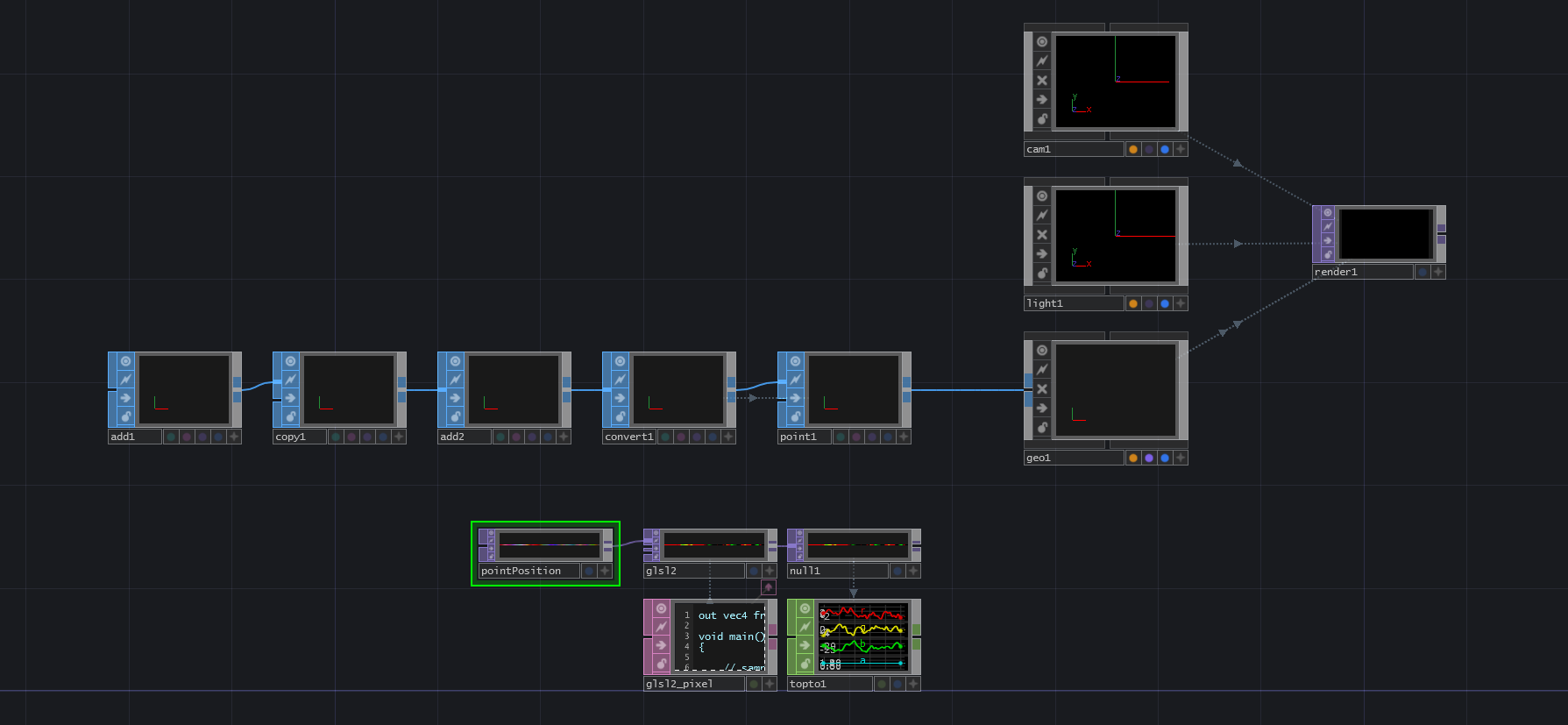
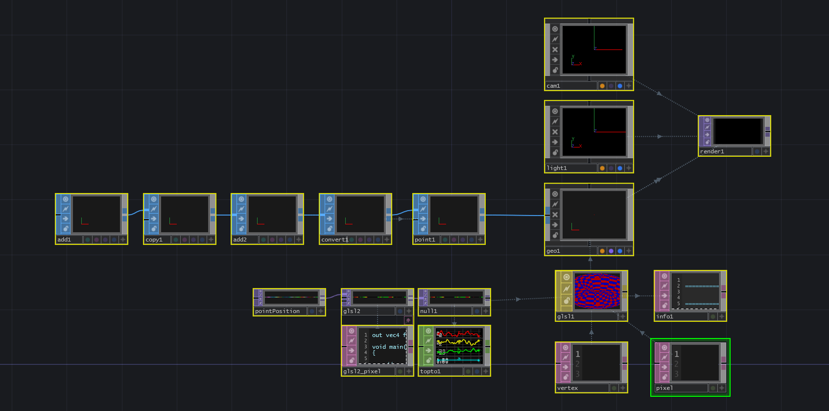
Next, create a 'GLSL MAT' operator, an 'Info DAT', and two 'Text DAT''s. Reference the 'GLSL MAT' in the 'Info DAT''s 'Operator' parameter to help debug any errors. Name one of the 'Text DAT''s 'vertex' and the other 'pixel'. These will be the GLSL vertex and pixel shaders. Reference 'vertex' in the 'GLSL MAT''s 'Vertex Shader' parameter, and reference 'pixel' in the 'GLSL MAT''s 'Pixel Shader' parameter. Then we need to reference the 'GLSL TOP' we created. To do so, on the 'Samplers 1' parameter page of the 'GLSL MAT', add 'sPointPosition' to the first 'Sampler Name' parameter, and add the name of the noise texture to the first 'TOP' parameter. In the example file, a 'Null TOP' named 'null1' was added after the 'GLSL TOP', and that is the operator name that is referenced in the 'TOP' parameter. Be very careful with the 'Sampler Name' parameter, as this will the name used in the code and if it is different than the code, you won't see any outputs as you won't be able to reference the particle position. Finally, on the 'Vectors 1' page of the 'GLSL MAT', add 'uPointsPerInstance' to the first 'Uniform Name', and enter '1.0 / 1000' as the first value of the parameter 'value0x'. This last vector will be used in the shader to scale the point index from 0-1000 to the normalized 0.0 to 1.0 UV co-ordinate when sampling the point position noise texture. With that setup complete, we can move from step 6 to step 7.
{width=100%}
From here, we will finish all the remaining steps in the GLSL shaders. First, edit 'pixel', the 'Text DAT' we will use to hold the pixel shader, and enter the follow:
layout(location = 0) out vec4 fragColor;

void main()
{
// shade pixel white
fragColor = vec4(1.0, 1.0, 1.0, 1.0);
}
This is a very basic pixel shader as we've seen earlier in the chapter, and all it does is shade any incoming pixels white. This completes step 7.
Edit 'vertex', the 'Text DAT' we will use to hold the vertex shader and enter the following:
// setup inputs
uniform sampler2D sPointPosition;
uniform float uPointsPerInstance;
in float pointIndex;

void main()
{
    // create the uv from point index
    vec2 uv;
    uv.x = (pointIndex * uPointsPerInstance) + (uPointsPerInstance * 0.5);
    uv.y = 0.5;

    // sample the noise texture using the uv
    vec4 newPosition = texture(sPointPosition, uv);

    // set point size to your liking
    gl_PointSize = 1.0;

    // move point from object space to screen space and output to gl_Position
    vec4 worldSpaceVert = TDDeform(newPosition);
    gl_Position = TDWorldToProj(worldSpaceVert);
}
Once you enter and save that code, you will see the particle system creating a ribbon-effect using the generated noise. Let's go through this vertex shader.
The first 4 lines setup the noise texture as a 'uniform sampler2D', the 'uPointsPerInstance' value as a 'uniform float', and the incoming point index attribute as an incoming float:
// setup inputs
uniform sampler2D sPointPosition;
uniform float uPointsPerInstance;
in float pointIndex;
The next few lines in the code create the UV to use when sampling the noise texture. To create the X location of the UV, we first take the incoming point index and multiply it by 'uPointsPerInstance', which is 1 / 1000. This gives us the location to sample from the 0.0 to 1.0 range. A key thing to remember when creating UV's manually is that the UV co-ordinates have infinite precision, so a UV of 0 along the X axis isn't the first pixel, it is the left edge of the first pixel, which will cause visual errors as the shader will then interpolate 50\% of the first pixel and 50\% of whatever is to the left of the first pixel (depending on the repeat parameters set). Because of this, we need to offset our sample by half of the sample step 'uPointsPerInstance', which is why we add the result of 'uPointsPerInstance' multiplied by 0.5 to the location we calculated by multiplying 'pointIndex' and 'uPointsPerInstance'.
To recap that:
We need to convert the point index from 0 - 1000 to the UV co-ordinates 0.0 to 1.0
Do that by multiplying the point index by the result of 1 / 1000, which gives us our sample step along the 0.0 to 1.0 range
Then add half of 'uPointsPerInstance' value (which is half of a single sample step) to offset our sampling so that we are samlping the middle of each pixel and not the left most edge
Finally, because we know the texture is only 1 pixel tall, we can set 'uv.y' to 0.5 (again, because we don't want to sample the edge of the pixel, we want to sample the midle of it).
// create the uv from point index
vec2 uv;
uv.x = (pointIndex * uPointsPerInstance) + (uPointsPerInstance * 0.5);
uv.y = 0.5;
The next thing to do is use the UV co-ordinates to sample the noise texture:
// sample the noise texture using the uv
vec4 newPosition = texture(sPointPosition, uv);
Before we finish assigning the new point position, we use this handy piece of GLSL code to quickly adjust the size of the particles. We're able to do this because earlier, we used the 'Convert SOP' to set the particle types to sprites (as this code only works with sprites).
// set point size to your liking
gl_PointSize = 1.0;
Finally, the code below takes our 'newPosition' values from object space, uses 'TDDeform()' to move them to world space. Then 'TDWorldToProj()' is used to convert the world space point to screen space points, which are assigned to 'gl_Position', which is the built-in output for each points position.
// move point from object space to screen space and output to gl_Position
vec4 worldSpaceVert = TDDeform(newPosition);
gl_Position = TDWorldToProj(camSpaceVert);
With that, we've finished the first goal, which was to move particles with textures. Although this may not seem like a traditional particle system, these steps lay the foundation for the next implementations.
{width=100%}
12.7.3 Using Source Geometry
Now that we have a basic grasp on moving particles using textures, we can add in a piece of geometry and use its positions as starting positions for our particle system. In this exercise, we'll replace our 'Add SOP' with a 'Grid SOP' (with the same point count) and add some noise to each particle position. These are the steps we will follow:
Create a texture from the point position data of 'Grid SOP'
Use this texture to position our particles in the point positions of the 'Grid SOP'
Apply the previous noise texture on the new positions to create an effected grid
It is best to read this text while examing the example project '02_Source_geometry.toe', because I will refer to certain operators by their names in the example project.
The first step is to create a texture from the point position data of the 'Grid SOP'. The source of point positions in the first example was an 'Add SOP', a 'Copy SOP', and another 'Add SOP'. Start by removing these and replacing them with a 'Grid SOP' with the 'Rows' parameter set to 100 and the 'Columns' parameter set to 10. This combination of rows and columns will create a grid with the same number of points as our previous example.
The next step is to get all the point positions from the 'Grid SOP' using a 'SOP to CHOP'. Create a 'SOP to CHOP' and set the 'SOP' parameter to the name of the 'Grid SOP' which in this case is 'grid1'.
This creates a CHOP with all the point positions as separate channels. We can translate these XYZ channels into RGB channels of a texture by using the 'CHOP to TOP'. Create a 'CHOP to TOP' and set the 'CHOP' parameter to the name of the 'SOP to CHOP', which in this example is 'sopto1'. Make sure the set the 'Pixel Format' to '32-bit float (RGBA)' in the 'Common' settings of the 'CHOP to TOP', as we will be feeding this into the GLSL shader and want it to continue outputting a 32-bit texture. Connect the output of the 'CHOP to TOP' to the second input of 'glsl2', the 'GLSL TOP' we were using in the last example to scale the noise values.
This complete the first step of the example.
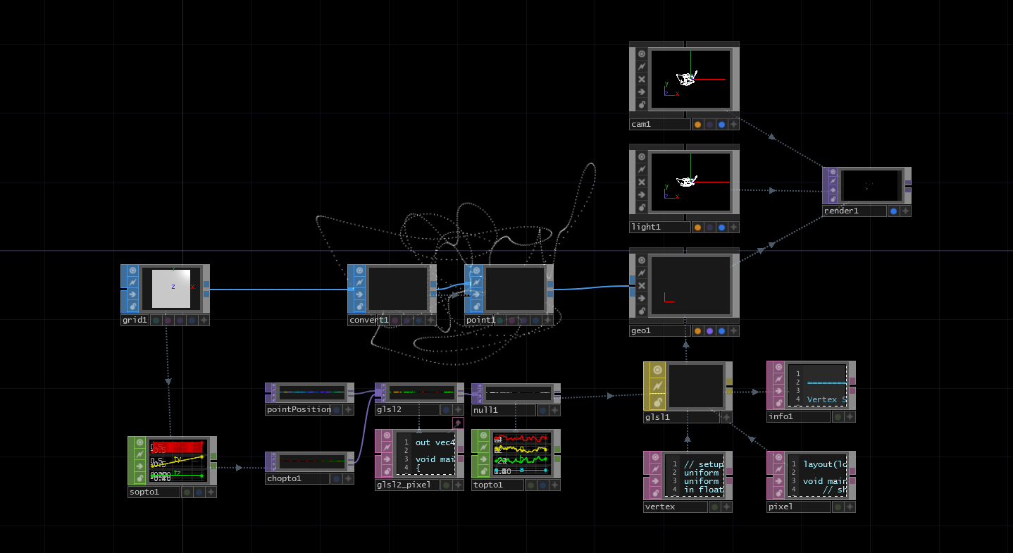
{width=100%}
Now that we have a texture, let's make a few additions to our shader. Below is our final shader from the previous example:
out vec4 fragColor;

void main()
{
// sample the input
vec4 inPosition = texture(sTD2DInputs[0], vUV.st);

// scale each color channel (the XYZ of the vector) separately
vec4 outPosition = vec4(inPosition.x * 5.0 - 2.5, inPosition.y * 5.0 - 2.5, inPosition.z * -5.0 - 20.0, 1.0);

// output the new position
fragColor = outPosition;
}
We'll start by adding a line to sample the new texture with the 'Grid SOP' position data. Insert this line after line 7 (we will review the full code at the end):
vec4 gridPosition = texture(sTD2DInputs[1], vUV.st);
This creates a new 4-part vector with our XYZ data that is connected to the second input (remember the inputs are indexed starting at 0). If you'd like to visualize this very quickly, change the last line temporarily to:
fragColor = gridPosition;
This will move all of the particles to the static points on the 'Grid SOP'. Before continuing, make sure the change the final line back to:
fragColor = outPosition;
Now we're going to focus on this line:
vec4 outPosition = vec4(inPosition.x * 5.0 - 2.5, inPosition.y * 5.0 - 2.5, inPosition.z * -5.0 - 20.0, 1.0);
Previously, we were taking the noise values, scaling them to make them interesting, then offsetting them to sit nicely in the camera's view. Our goal now is to take the incoming grid positions, and effect them with the noise. To do so, we can use a line like this:
vec4 outPosition = vec4(gridPosition.x + (inPosition.x * 0.1), gridPosition.y + (inPosition.y * 0.1), gridPosition.z + inPosition.z, 1.0);
Inside each part of the 'vec4', we're taking the 'Grid SOP' XYZ and adding to it the XYZ of the noise texture. The only extra thing we've added here, is that before adding the X and Y values of the noise, we're scaling them down, as it makes it a bit easier to see the 'Grid SOP' shape in the render. The full shader code should look like this:
out vec4 fragColor;

void main()
{
// sample the inputs
vec4 inPosition = texture(sTD2DInputs[0], vUV.st);
vec4 gridPosition = texture(sTD2DInputs[1], vUV.st);

// add scaled noise texture values to the grid position values
vec4 outPosition = vec4(gridPosition.x + (inPosition.x * 0.1), gridPosition.y + (inPosition.y * 0.1), gridPosition.z + inPosition.z, 1.0);

// output the new position
fragColor = outPosition;
}
Once you save, you should the columns of the grid being effected by the noise texture.
{width=100%}
Feel free to experiment by replacing the 'Grid SOP' with another geometry with 1000 points.
12.7.4 Adding Velocity
In this section, we're going to remove the random noise that is driving the particles and add a constant velocity. We won't spend much time going into depth on some of the physics concepts, if they're new to you, we recommend either:
- Nature of Code which is a great Processing book about modeling natural forces
- Khan Academy for learning the physics concepts on their own
We're going to make some simple UI controls that will allow us to add a constant velocity in XYZ space to all the particles. How the particles are controlled is important because data from the last frame is added to the current frame to find the new positions. Think about a particle traveling over a few frames. For every frame the particle needs to know where it was the last frame so it can add the velocity and calculate it's new position. In the previous examples, the noise only ever had the current frame worth of data.
The main element we're going to add in this example is a feedback loop so that we can continuously feed in the last frame's data, update the texture with new positions, then feed it back as the input.
You can follow along with example 01_adding_velocity.toe in the folder TouchDesigner Example Files/12.7.4.
Start by deleting the 'Noise TOP' and unplugging the chopto1 from the 'GLSL TOP'. Follow these steps:
- Create a 'Feedback TOP'
- Connect the output of
chopto1to the input of the 'Feedback TOP' - Connect the output of the 'Feedback TOP' to the first input of the 'GLSL TOP'
- Set the 'Target TOP' parameter of the 'Feedback TOP' to the name of the 'GLSL TOP', in the example project this is
glsl2
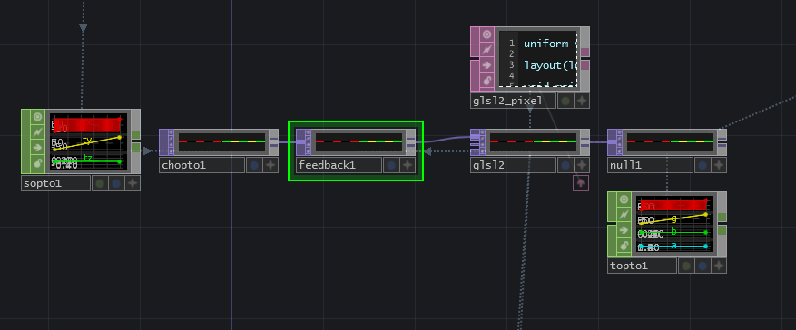
This should look like the image below:
{width=100%}
Now let's create a new uniform on the 'Vectors 1' page of the 'GLSL TOP' parameters. Name it it uVel and leave the values at 0.
You can see the final shader if you skip down a little bit, but here are the individual changes explained.
Add a line to get our new uniform value at the start of the shader:
uniform vec3 uVel;
We're going to change the name of our vec4 output from fragColor to oPosition, which is a short name for 'output position'.
Then, instead of sampling noise positions and grid positions, we're going to sample the new input positions that are fed back to the shader from the 'Feedback TOP':
vec4 pos = texture(sTD2DInputs[0], vUV.st);
We will add our new velocity value to the previous point position:
pos.xyz += uVel.xyz;
And finally, output the new point position:
oPosition = pos;
The final shader for this example will look like this:
uniform vec3 uVel;

out vec4 oPosition;

void main()
{
    // get input positions
    vec4 pos = texture(sTD2DInputs[0], vUV.st);

    // add our single velocity values to every point position
    pos.xyz += uVel.xyz;

    // output the new point position
    oPosition = pos;

}
The final elements that we need are an interface to change the uVel uniform parameter, and a button to reset the particles by resetting the feedback.
In the example, we created a 2D slider for the XY velocity of the particles and a slider for the Z velocity. You can experiment with other kinds of sliders and buttons, as long as you reference the channel values in the first three values of the uVel uniform on the 'Vectors 1' page of the 'GLSL TOP' parameters.
The script you'll add to your reset button will vary depending on the type of interface you create, but there will be one line that should always be at the end of it. This line will pulse the 'Reset' parameter of the 'Feedback TOP', which will then clear the feedback and pass through the original point positions of the grid again. In the example reset script, the UI elements are all reset to a 0 position, and then the 'Feedback TOP' is reset.
12.7.5 Random Velocity
Now we have the most basic particle system imaginable: a system where all the particles move with the same constant velocity. In this section we're going to give each of the points their own random velocity instead of controlling them with UI elements. This will create the effect of a particle explosion from the 'Grid SOP'.
Start by removing the uVel uniform from the 'GLSL TOP' and clearing the parameters that reference our UI elements. Your Vectors 1 parameter page of the 'GLSL TOP' should be clear.
Next, delete the sliders/UI elements created to control the particle velocity but do not delete the reset button. We will continue to use the reset button in this example.
Depending on what kind of elements you had created to control the particles, we'll need to remove any of the Python code associated with them from the 'Panel Execute DAT' connected to the reset button. Inside the def offToOn callback you should only have a line that resets the 'Feedback TOP':
op('feedback1').par.resetpulse.pulse()
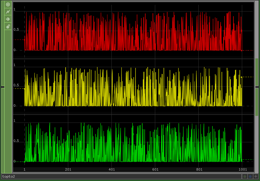
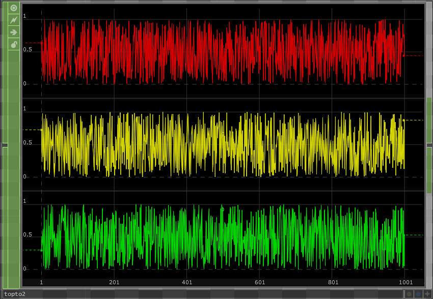
The final element we need in the network is a 'Noise TOP' with a resolution of 1000 pixels by 1 pixel, to match the resolution of our 'CHOP to TOP'. Set the 'Noise TOP' type to Random (GPU). Turn of the Monochrome toggle. Set the Amplitude to 0.5, and set the Offset to 0.5. Changing these two parameters is an easy way to move the noise values from the range of 0 and 1 with a floor of 0 to a range of 0 and 1 with a 0.5 center.
To visualize this, it is a move from this kind of noise:
{width=100%}
To this kind of noise:
{width=100%}
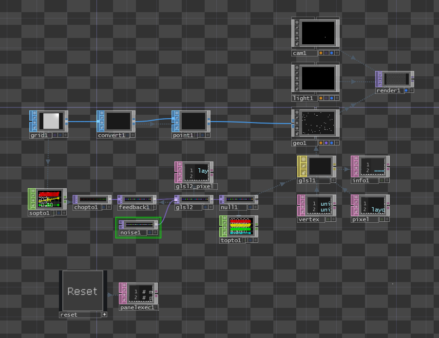
With these parameters set, plug the 'Noise TOP' into the second input of the 'GLSL TOP'.
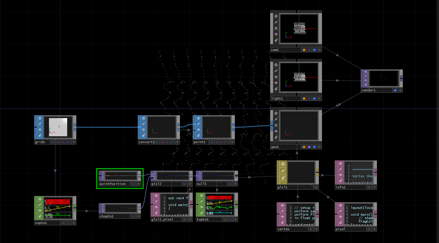
Your network should now look like this:
{width=100%}
In our shader, we only have to make a few changes.
After the line where we sample the input positions from the grid, we'll add a line that samples our noise texture and creates a new vec4 named velocity:
vec4 velocity = texture(sTD2DInputs[1], vUV.st) * 2 - 1;
This should look very familiar by now. The * 2 - 1 at the end is some simple math that changes the noise range of 0 and 1 to a range of -1 and 1.
Now in the next line of code, instead of adding the uVel uniform, we'll add the new velocity vector:
pos.xyz += velocity.xyz;
Now you can click your reset button and watch the particle system explode away from the 'Grid SOP' points. Experiment with the 'Noise TOP' settings and the ranging math in the shader to see how you can create different results.
{pagebreak}