10.3 Creating an Output Raster
As a general rule, to get the best performance possible, one should always strive to only use 1 Window COMP at a time. This doesn't apply while programming, but when it comes to deployment and performance, having more than one window open will greatly decrease the system's performance. So what should be done if there are multiple outputs with different positions and rotations?
The answer is to create a raster for the output and create a single, all-encompassing, window that will span all of the real-world outputs.
This is more simply expressed with an example. In this example scenario, there are four SXGA+ projectors, each with a resolution of 1400x1050. In the real-world setup, there are two projects beaming horizontally on side walls, and two projectors beaming vertically, and edge blended, on the center wall. The diagram below illustrates the desired setup.
{width=100%}
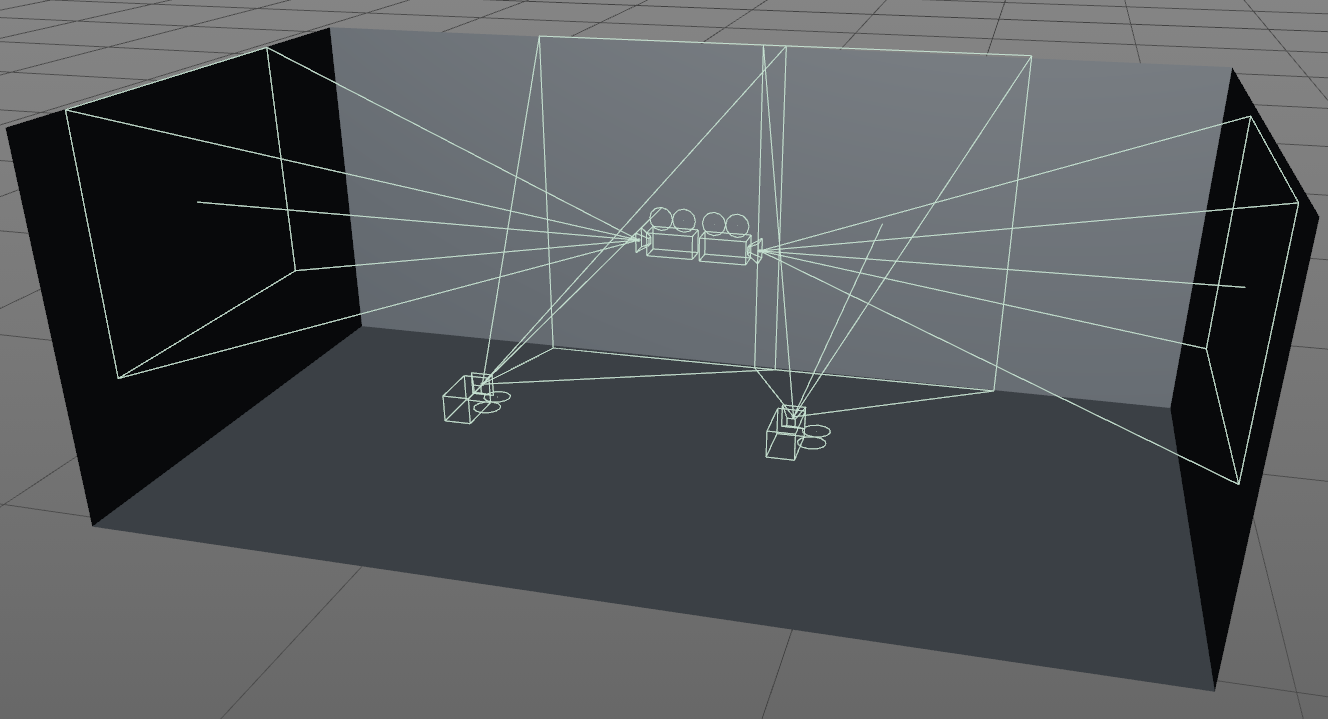
This setup isn't particularly complex, thus knowing how to deal with it most effectively is important. Let's take this setup, and lay it out in 2D.
{width=100%}
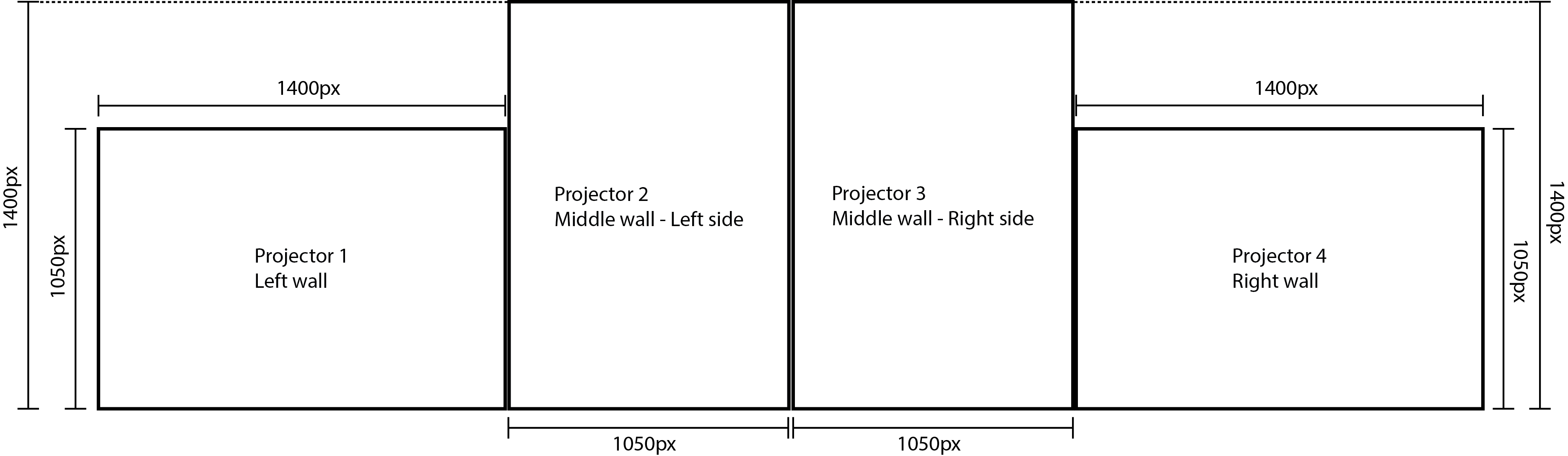
A beginners's first instinct might be to use four Window COMPs because there are four outputs, two of which need to be rotated. The challenge is finding the most efficient layout for these four canvases, to create a single raster. In this instance, because all four outputs are the same resolution, an easy solution is to make a 2x2 grid.
{width=100%}
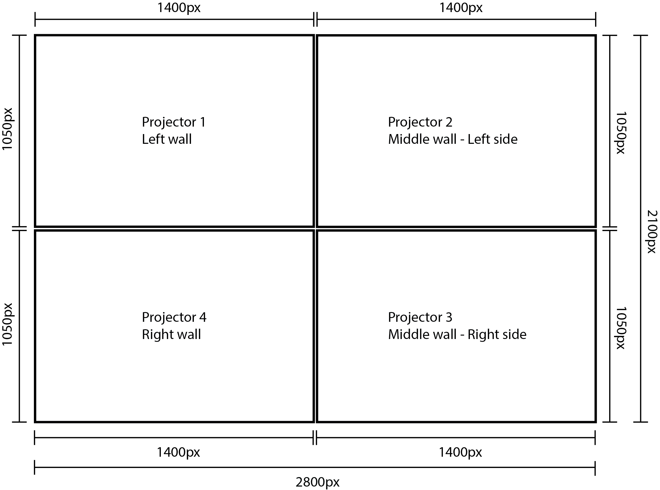
In the above diagram, all of the outputs are placed into a single raster. This setup can efficiently use one Window COMP that is 2800x2100 pixels. At this point, the nVidia or AMD control panel should be used to create a similar setup out of the monitors in Windows, which should then be connected to the correct outputs on the graphics card.
The next step is to prepare this raster inside of TouchDesigner. Open example 'Raster.toe'. There are a few things to note from the start. For the example, some very basic dummy content has been created, and will represent where real content would go. 'Content1' is for the left wall projector and is 1400x1050 pixels. 'Content2' is for the middle set of projectors and is 2100x1400 pixels. 'Content3' is for the right wall projector and is 1400x1050 pixels. All of the canvas building happens inside of the 'canvas' Container COMP.
In the 'canvas' container, the signal path can be followed from left to right, and from top to bottom, like a waterfall. The first step is to create a blank raster that content can be composited on. There is a Constant TOP set to 2800x2100 pixels at the top left of the Network for this purpose. Using an Over TOP, the first piece of content is placed, for the left wall projector, in its appropriate position, according to the diagram above. This is done using the 'Translate' parameter of the Over TOP. Projector 1: done!
The middle wall has two projectors that are edge blended together. Because a few operations need to happen on the raw content, there is a container name 'crop'. This keeps the operations encapsulated, neat, and easy to find. Inside of 'crop', three main operations are performed. The first is that the big piece of content is cut it in half, so that each projector can display half of the image. Since the projectors are positioned vertically in the installation, but are positioned horizontally in the raster, the 'Flop' parameter of the Flip TOP is used to turn the canvas on its side. The settings for the Flip TOP will always end up being different depending on hardware setup, so be prepared to try different Flip and Flop settings to get the correct content orientation.
Side note: Most beginners have trouble rotating a full canvas. The first instinct is to use the Transform TOP, but it is important to note that the Transform TOP will transform the pixels inside of a canvas. This is where the 'Flop' parameter of the Flip TOP comes in. It will fully rotate the canvas.
Since this example isn't dedicated to edge blending, the 'edge_blend' containers are just place holders that create the visual effect of a blended edge.
With all the cropping, rotating, and blending done, the two projector outputs are ready to be composited onto the raster. Using the same technique as before, an Over TOP with a modified 'Translate' parameter correctly positions the two pieces of content. Now Projector 2 and 3 done as well!
The final projector is as simple as the first, and using the trusty Over TOP, the final piece of the puzzle is positioned.
As mentioned in an earlier chapter, it is best practice to use Container COMPs instead of TOPs as the source for Window COMPs. In this project, there is a container that is 2800x2100 pixels that holds the completed raster. The 'final' container is set as the Window COMPs 'Operator', the 'Borders' setting is turned off in the Window COMP, and the window size is set to 2800x2100 pixels. With that, the project is ready to be output to the above, 4 projector, setup.
{pagebreak}